 Español
 Français
 English GB
 Português PT
Shopping Cart
There are no more items in your cart
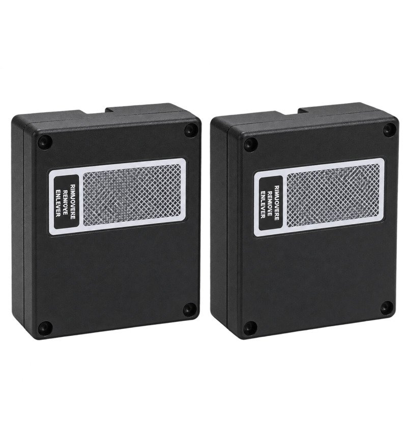
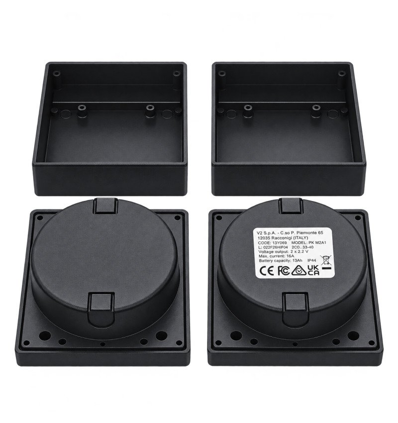
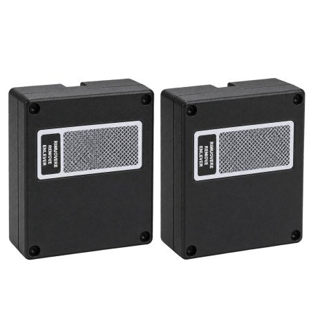
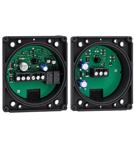
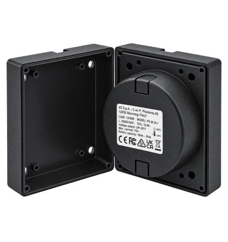
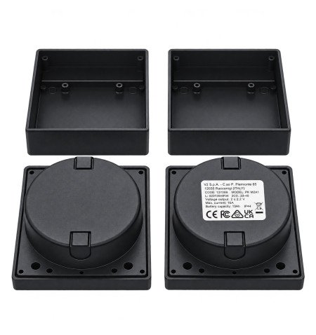
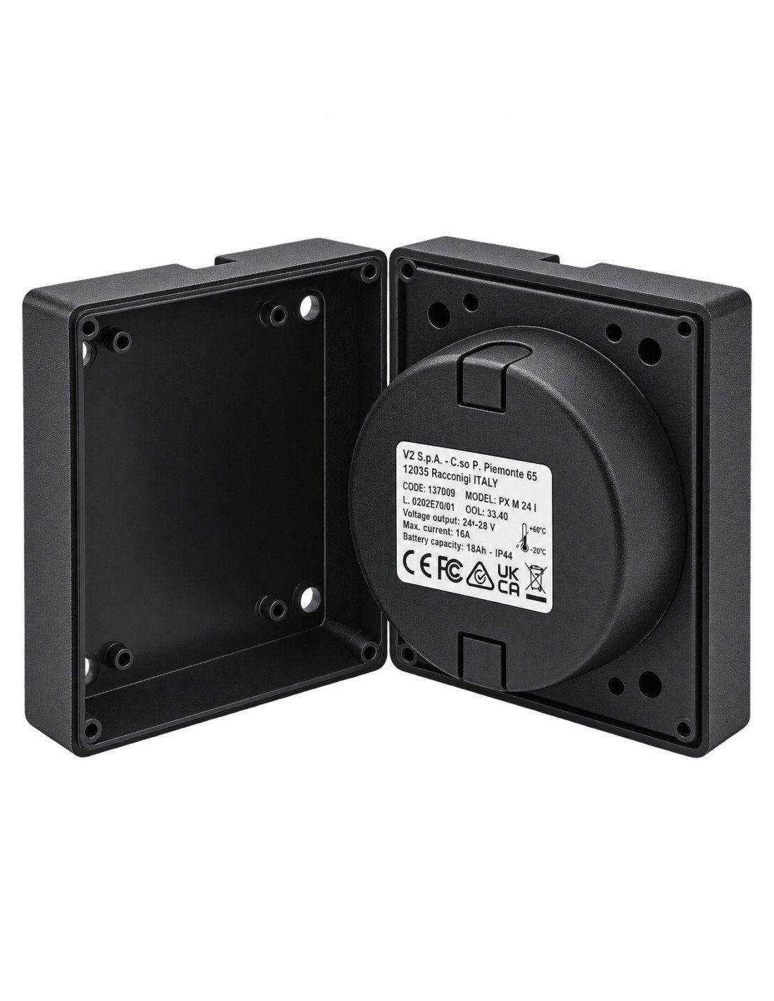
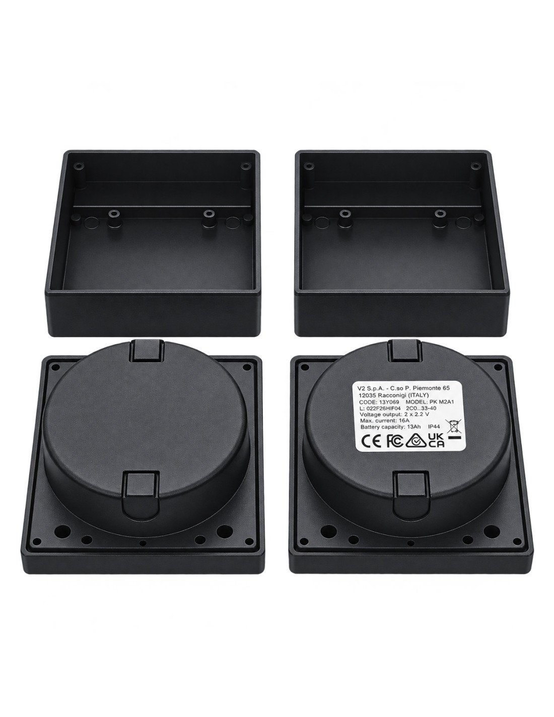
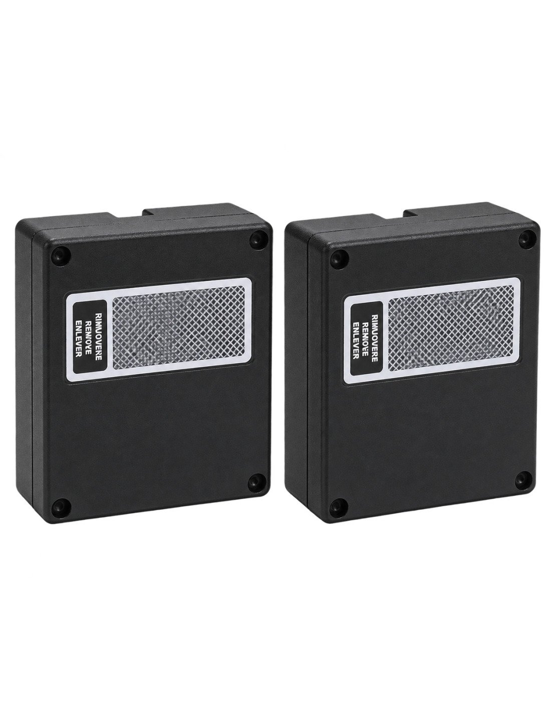
Surface photocells V2 DFN to embed self-aligning and synchronized

13A001
€49.00
VAT excluded
59,29 €
Tax incl.
V2 PX M 24 I are safety booths, self-aligning and synchronized, with feeding 12 to 24 V AC / DC and a maximum optical range of 25 meters.
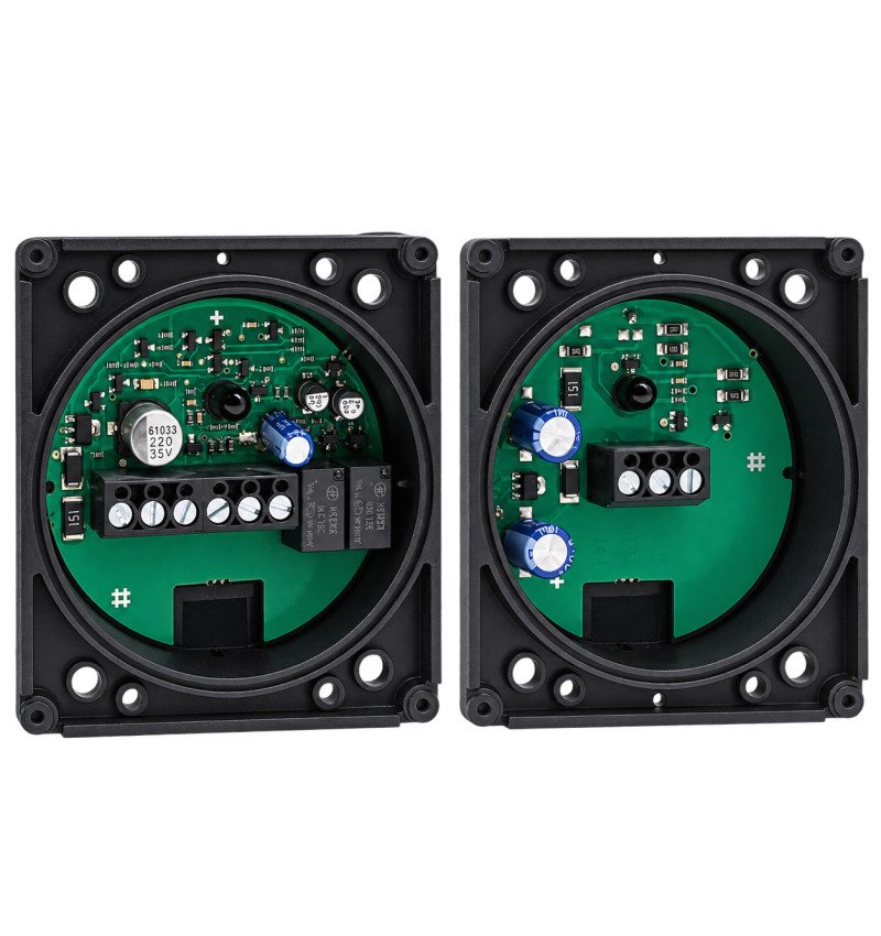
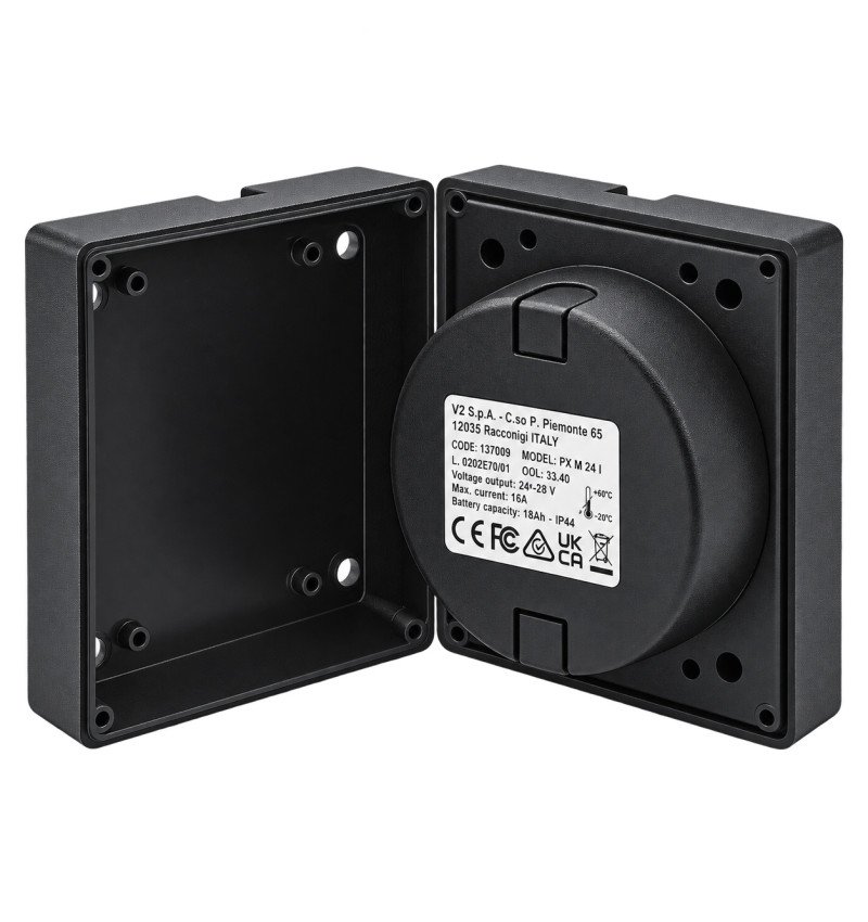
This system is composed of a TX transmitter and a RX receiver and is designed to be integrated into pillars, walls or other surfaces, achieving a more discrete and protected embedded installation.

We ship your order within 24/72 hours

Secure payment: Card, Bank transfer, Bizum

Fast shipping from Spain Except bulky
V2 PX M 24 I are safety booths, self-aligning and synchronized, with feeding 12 to 24 V AC / DC and a maximum optical range of 25 meters.
This system is composed of a TX transmitter and a RX receiver and is designed to be integrated into pillars, walls or other surfaces, achieving a more discrete and protected embedded installation.
The photocells detect people, vehicles or obstacles that interrupt the infrared beam on automatic doors, gates, barriers and other access control systems. The LED built into the receiver facilitates the alignment and commissioning.
| Scope and food: until 25 meters of optical scope and operation 12-24 V AC / DC. |
Advantages of photocells V2 Px m 24 I
- System of security consisting of TX transmitter and RX receiver.
- Maximum optical range of 25 meters.
- Multivolt feed 12 to 24 V AC / DC.
- Designed specifically for recessed installation.
- Self-relimating system with LED indicator on the receiver.
- Synchronization function to install two close couples without interference.
- Relay output with NC contacts, com and not.
- Suitable for indoor and outdoor installations.
- Compact dimensions of 76 × 66 × 30 mm.
Applications
The px M 24 I photocells allow people to detect people, vehicles or obstacles that interrupt the infrared beam between the transmitter and the receiver. They are indicated to protect and control areas of step in:
- Automatic doors
- Sliding and swing gate.
- Garage doors.
- Access barriers.
- Pedestrian and vehicle accesses.
Synchronized operation
The synchronization circuit allows you to install two couples of photocells very close to each other, reducing the risk of interference between the beams.
- With alternating current feeding: It is possible to use synchronized operation by investing the polarity between the first and the second couple.
- With continuous current feeding: Couples work without synchronization and should be installed in reverse position to each other.
| Important: The power of the TX transmitter and the RX receiver must be in phase. If the receiver LED flashes, check the correspondence of the power connections. |
Technical data
| Feature | Specification |
|---|---|
| Manufacturer | V2 / Arable |
| Model | Px m 24 I |
| TYPE | Synchronized and self-aligned photocells |
| Type of assembly | Built- |
| Maximum optical scope | 25 m |
| Feed | 12-24 V AC / DC |
| Signal | Infrared modulated at 833 Hz |
| Wavelength | 950 nm |
| Relay | 1 to maximum at 30 v dc |
| TX transmitter consumption | 20 m |
| Consumption of the RX receiver | 25 m |
| Operating temperature | From -20 ° C to +60 ° C |
| Dimensions | 76 × 66 × 30 mm |
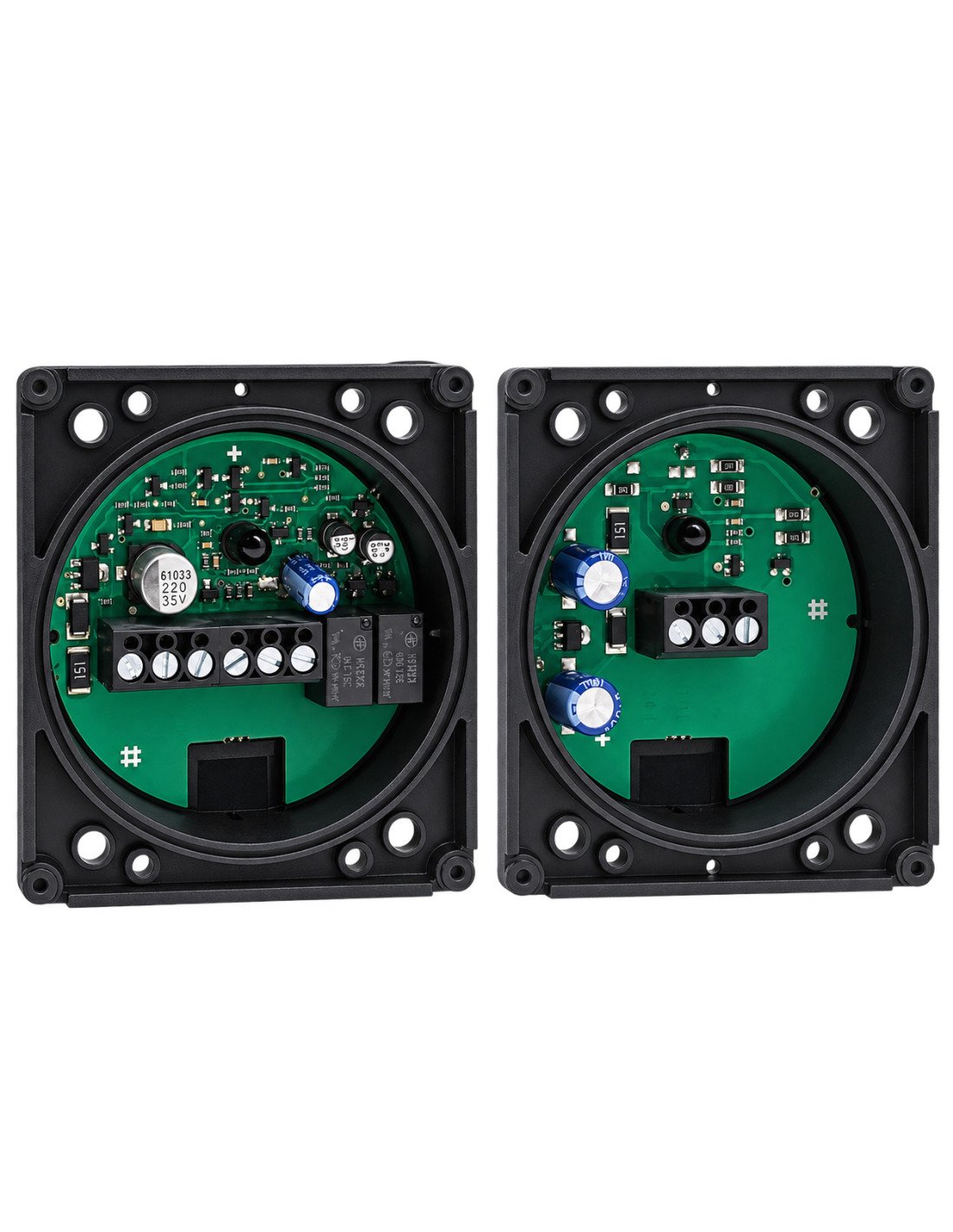
Electrical connections
TX transmitter
| Terminal | Function |
|---|---|
| 1 | +24 V |
| 2 | +12 V |
| 3 | Gnd |
RX
| Terminal | Function |
|---|---|
| 1 | +12 V |
| 2 | +24 V |
| 3 | Gnd |
| 4 | Contact NC |
| 5 | Contact com |
| 6 | Contact No |
Receiver LED Indicator
| LED | Meaning |
|---|---|
| On | Transmitter and receiver correctly aligned |
| Off | Drive beam or photocells without aligning |
| Flashing | TX and RX power out of phase |
Installation recommendations
- Install the confronted transmitter and receiver, on the same geometric axis and at the same height.
- Use flat, firm and properly aligned surfaces.
- Prevent the RX receiver from being directly oriented towards the sun.
- Check the receiver LED during alignment and commissioning.
- Interrupt the infrared beam several times and verify that the LED goes out and the relay commute.
- Set the adhesive joint correctly to preserve the sealing of the housing.
| Intense solar exhibition: The manufacturer indicates a specific configuration of the gasket on the RX receiver lens. In this configuration, the maximum range is reduced to approximately 13 meters. |
Product content
- 1 TX transmitter V2 Px m 24 I.
- 1 RX receiver V2 Px m 24 I.
| Security: The installation, connection and verification of the photocells must be performed by qualified personnel. Disconnect the automation power before handling the wiring. |
Tap to zoom